Although a difficult decision, it was time for a new museum.
The new Fort Worth Museum of Science and History replaced the existing museum building on the same site in November 2009.
The museum has 166,000 gross sq. ft composed of one-story and two-story spaces. The building consists mostly of exhibit spaces, classrooms, support areas, public spaces and dining areas. Three unique steel structures are the main massing of the building design: the new domed Noble Planetarium, the Energy Gallery roof, and the main entrance, called the “Urban Lantern.”
Domed Noble Planetarium
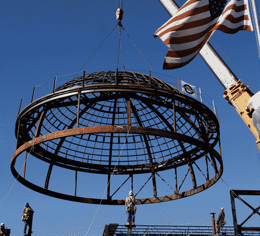 <<Arriving on site as individual pieces, the Noble
Planetarium Dome was assembled on the ground, then lifted into place.
The new Noble Planetarium is a state-of-the-art facility that sports a 50-ft-diameter steel-framed “ribbed dome,” which was completely fabricated on the ground and lifted into place. That operation was featured prominently in the Dallas Morning News and was the symbol of construction progress for some time.
The dome is constructed of arched ribs, joined together with a compression ring at the top and tension ring at the bottom. It has 8-in. wide-flange column ribs with 2-in.-diameter transverse pipes encircling the dome in concentric rings. The rings serve as lateral bracing for the vertical arched members, add rigidity for the dome, and provide support for the dome cladding.
The dome members were delivered as individual pieces ready to be assembled like a kit of parts. A staging area next to the final location was set up for the erection process where the steel erector welded the elements together on the ground.
All vertical wide-flange ribs were welded to the tension ring at the bottom and converged to a compression ring at the top of the dome. Once the ribs were in place and the transverse pipes were installed, the resulting configuration was a semi-rigid grid that resisted racking and was stiff enough to be lifted into its final location.
Additionally, smaller tubes and angles were connected to the main frame to accept the dome cladding. This additional framing enhanced the smoothness of the dome to prevent ridges or offsets from occurring between cladding panels.
Months earlier, additional analysis and careful coordination among the structural engineer, erector and contractor had been performed to allow the nearly lawless installation to occur. Hanging locations were determined and analyzed for performance during the 60,000-lb lift. The erector performed an in-depth study of shoring and the hoisting procedure that ended in an evolution that appeared to spectators as a quick and easy solution.
The planetarium’s second floor framing was carefully analyzed and designed to minimize vibration interference from exterior distractions to ensure successful operation of the projector. Locating a column directly below the mechanism and increasing the concrete slab thickness pro-vides the required platform stability and helps mitigate vibration interference with the projector.
The Energy Gallery Roof
 <<To help control gravity load deflections in the Energy Gallery roof’s 55-ft cantilever, engineers provided 6-in.-diameter pipe columns tucked behind mullions.
The Energy Gallery roof was designed with 7-ft-deep steel trusses, supporting an 8-ft-tall ribbon of brick. The visual expression of the structure is a 50-ft cantilever with a 15-ft backup span and support. To control gravity load deflections and high stresses, the “cantilever” is supported by small intermediate columns consisting of 6-in. pipe located behind window mullions.
This configuration contributed to significant calculated wind sways at the end of the cantilever in the transverse direction, because the only wind bracing in the trans-verse direction is at far end of the space.
The high roof uses horizontal X-bracing to maximize the rigidity of the diaphragm to transfer the lateral loads to the rear bracing system. The low roof diaphragm minimizes the sway of the structure and helps distribute the lateral loads.
Close coordination with the glazing manufacturer’s engineer was required to accommodate the anticipated structural movements. The connections for the tall windows were designed to accommodate larger than usual horizontal and vertical movements. Attention to these details of the design by the structural engineer and the glazing manufacturer’s engineer was critical to its success.
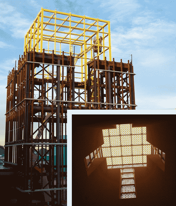
The Urban Lantern
The Urban Lantern is the pride of the museum. Its proportions and interior volume create a space that is tall, open and impressive. The Lantern is 76 ft tall and topped with a glass box made of 97 yellow-fretted glass panels, each measuring 5 ft 7 in. square and weighing 500 lb.
The Lantern is a critically important element because it is the gateway to the museum. Design architect Ricardo Legorreta expressed this by saying, “Light symbolizes knowledge, creativity, imagination and spirituality. Color, on the other hand, for us means passion for life, humanism and happiness.”
Careful computer modeling and structural analysis were conducted using RISA to ensure the framing system and brick sup-ports would perform as expected. The basic approach was to create a braced tower with an open interior. Usually a tower would have horizontal cross-bracing or floors to prevent racking and distribute lateral loads, but this was not an option. Instead, engineers used the building’s adjacent low roof diaphragm and a 5-ft 10-in.-wide reinforced concrete slab on composite deck at the tower’s second level to provide racking strength. This essentially created a rigid floor slab with a big hole in the middle of it. Additionally, the roof corners at higher levels have similar concrete slabs to enhance stiffness.
Full-height cross-braces were provided at the corners of the tower for stability. Horizontal HSS12r6 girts at 10-ft vertical spacing tie the tower together and provide connection points for the brick support system.
The exterior brick is supported by a system specifically designed not to have visible horizontal kickers so as not to obstruct the interior open space. Vertical HSS5r5 members spaced at 4-ft centers provide support for the brick shelf angles at each level. The horizontal HSS girts are designed to resist the moments and reactions from the vertical tubes induced by wind and the eccentric brick loads at each level.
The unique idea of Legorreta’s Urban Lantern incorporates a glass box to the top that glows at night, guiding its patrons to the museum’s front door. The structural engineer conceived the structural concept and design of the glass box at the top of the tower. Then Menomenee Falls, Wis.-based manufacturer Novum
Structures LLC implemented the design and built the glass box.
The loads calculated by Novum’s engineers were provided to the structural engineer to include in the overall building model.
This state-of-the-art glass system includes unique proprietary glass connections and expansion joints designed speciically for the
Fort Worth area. The end result accomplished the architect’s vision.
The Fort Worth Museum’s “extreme make-over” resulted in a facility that is world class and will be a source of pride for the city, museum and the designers for years to come.
No hay comentarios:
Publicar un comentario