A Kansas City’s new performing arts center is a showcase of outstanding steel-framed structures.
ATOP A HILL with a commanding view to the south and overlooking the revived Crossroads Arts District sits the newest addition to the Kansas City skyline, the Kauffman Center for the Performing Arts. This world-class entertainment venue has proven to be as challenging to design and build as it is expected to be beautiful and functional.
Scheduled to be completed and ready for the 2011 performance season, it will be the performance home for the Kansas City Symphony, the Lyric Opera of Kansas City, and the Kansas City Ballet.
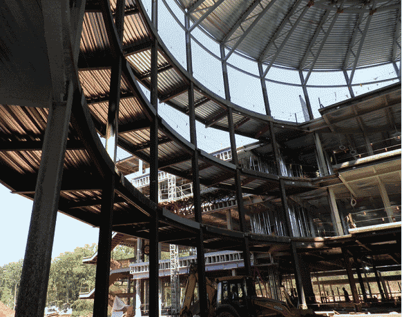
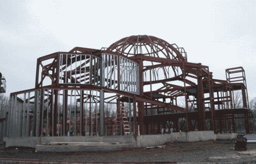
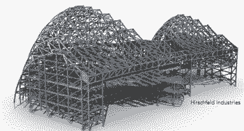
The Kauffman Center, envisioned by Muriel Kauffman of Kansas City as early as 1995, was finally brought to fruition by her daughter Julia Irene Kaufmann. The 285,000-sq.-ft facility consists of the 1,600-seat Helzberg Hall, for symphonic concerts, and the 1,800-seat Muriel Irene McBrien Kauffman Theatre for live stage performances. A third independent structure acts as a shell enveloping the two internal buildings. This unique architectural showpiece starts with a series of segmented vertical arcs forming the north wall and, from the top of the arcs, descends to the south with a gentle sweep ending with its signature cable-supported glass atrium.
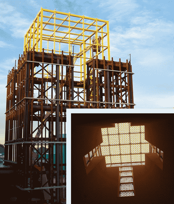
A Structural Framing Challenge The complex geometry and intricate connections required to connect the symphony of trusses and rolled beams resulted in hardly a 90° angle or straight piece of steel anywhere in the structure. Working as a subcontractor to J.E. Dunn Construction, Hirschfeld Industries was specifically selected as the structural steel contractor on this unique project because of its history of expertise with complex steel structures and in particular, the detailing, fabrication, and erection of elaborate trusses.
When completed, the structure weighed in at 3,989 tons of steel with 938 tons, or 24% of the total structure, being rolled steel. Rolling was equally split in the hard direction and in the easy direction. The top and bottom chords of the north wall vertical trusses are typically W14r99s and W14r211s rolled the easy way.
The top and bottom chords of the east/west trusses forming the roof of the shell and curved in the horizontal plane are typically
W14r90s rolled the hard way.
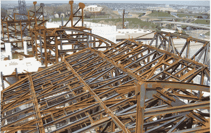
The concert hall, located on the east side of the site, consists of six levels of structural steel framing. The roof of this structure comprises six straight east/west trusses with clear spans ranging from 43 ft to 104 ft and an average depth of 14 ft, all supported by the concrete at Level 8. The organ trusses, aptly named for shaping the back wall of the organ chamber and echoing the shape of the outer shell, are located at the north end of the structure and consist of eight curved vertical trusses each approximately 47 ft in height extending from the concrete frame at Level 8 and connecting at the top to one of two trusses.
The second internal building, the proscenium theater, is located on the west side of the site and also consists of six levels of structural steel framing. This structure takes a slightly simpler approach with the roof structure consisting of only four straight east/west trusses with the northernmost truss tied into the concrete stage tower just to the north. A maze of multi-leveled curved catwalks is hung from the trusses.
The massive free-standing lattice shell forming the north wall is composed of 27 vertically curved north/south trusses rising to a height of 139 ft above the ground. Stretching between the top of the trusses and the box truss and defining the extreme south end of the steel structure is a series of W24s and W21s in the same vertical plane of each of the corresponding curved trusses.
Lateral resistance in the north/south direction is provided by six braced frames. Lateral resistance in the east/west direction is also provided by braced frames between the north wall trusses.
^
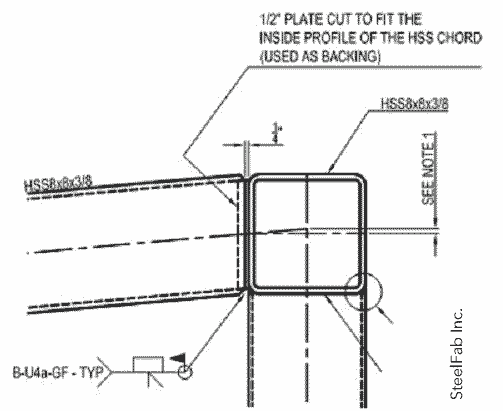
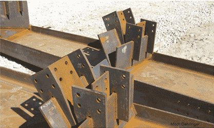
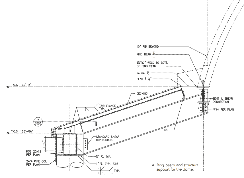
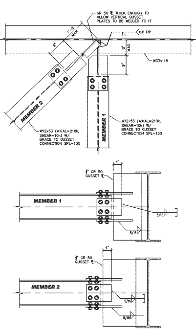
^A Many of the connections required multiple connection plates at various angles, posing challenges to both the detailer and the fabricator.
Acoustical Issues
Internal noise abatement is a critical consideration for dual-use venues such as this. Throughout the design and construction of the steel framing, careful consideration was given to avoiding the transfer of airborne noise as well as reverberations throughout the structure. The structural steel frames for the concert hall and theater were designed to be completely independent of the surrounding steel and concrete structure. A minimum acoustic joint of 2 in. at ground level, increasing to more than 6 in. at the top of the structure where the wind loads are more significant, was required between the inner buildings and the shell to control both airborne and structure-borne noise from entering the occupied space. Inspections conducted at the end of the erection of each sequence before vacating a specific area ensured that all temporary erection aids had been removed, thus preserving the acoustic isolation.
Detailing Connection Design
Consteel Technical Services, a wholly owned subsidiary of Hirschfeld Industries, used Tekla Structures, version 11.3, to provide highly accurate and interactive 3D computer modeling. With the structure being predominantly curved with braced frames on radial grid lines, it was by far the most complex and challenging structure the team had detailed. Structural Solutions,
Inc., designed the bolted connections using standard holes, per the erector’s requirement for immediate stability of the member, and slip critical bolts using a Class B faying surface. This resulted in a lower bolt shear capacity than for a bearing condition, so the quantity of bolts and size of the connections increased. However, it was required to eliminate any slippage in the connection and maintain the specified tension in the cable structure connected to the structural steel.
As many as 20 modelers, editors, and checkers were working in the Tekla model at any one time. Difficulties sometimes were encountered in avoiding clashes within the model, although these were not insurmountable problems. Unexpected problems were encountered, however, as the size of the model eventually approached the capacity of the software simply due to the complexity of the geometry. This was resolved by separating the model into two independent models—one for the concert hall and proscenium theater internal buildings and another for the external shell. The separation was done after the overall geometry had been established and shop drawings were being developed for the north wall, so there was little potential for any unknown clashes between the two models. However interface checks between the models still were done on a regular basis. (See sidebar “No More Maxing Out.”)
Throughout the detailing process, close collaboration between the design team, connection engineer, general contractor, and steel fabricator was a necessity in finalizing the structural design. Virtual meetings using online visual and audio links (via “Go to Meeting”) were an essential tool in bringing all parties together to visualize, design, and detail, the complex nodes with massive shear plates converging at different relative angles. As the 3D model was being developed, a detailer was brought in to work face to face with the design team, thereby incorporating the myriad of painting and fireproofing details on the steel as well as the exact location of the shop-attached pourstop. This preplanning was extremely beneficial to all and resulted in minimal field modifications and interruptions.
The lateral load resistance system, braced frames, consisted of wide flange diagonals connected to gusset plates with claw angle connections. The axial transfer forces across the joints were accommodated with massive end plate connections, some as long as 11 ft and up to 3 in. thick, with the flanges shopwelded to the end plates. This applied tension to the end plate bolts, reducing their effective clamping force and thus their slip resistance. The connections were carefully designed to ensure the required capacities were achieved, all while allowing for no connection slip at strength-level forces.
The cable supported glass system at the south end of the building introduced significant challenges to the connection design. Due to the high tensile forces required developed by the cable system, significant lateral and vertical loads were imparted into the external shell structure. No connection slip could be permitted in order to ensure the cables maintained their required tensile forces.
The connection design information was provided by the connection engineer to the detailer via connection tables for the simpler connections and intricate AutoCAD sketches for the more complicated joints. As the joint complexity increased, this process became iterative, with the connection engineer and detailer sharing copies of the 3D model until the joints were finally and completely detailed. Before the shop drawings were sent to the design team for approval, the connection engineer reviewed each one to ensure the connection design intent was correctly interpreted. The result was a steel structure of untold complexity erected with very few it-up issues in the field.
Fabrication
Dividing the structure into ten fabrication/erection sequences (one for the concert hall, one for the proscenium theater, and eight for the outer shell) and further subdividing the structure into 54 manageable shipping priorities allowed the construction site to maintain the erection at a productive rate while keeping the staging areas from being inundated with not-yet-needed assemblies.
To accommodate the compressed fabrication schedule, truss fabrication was done mostly in Hirschfeld’s Abilene, Texas, shops with the structural work being conducted in its San Angelo, Texas, shops. Trusses were shop assembled to the greatest extent possible still allowing the shipping of oversized and overweight assemblies to Kansas City via permit.
During crucial fabrication periods, Hirschfeld engaged a detailer to be present in the shops armed with the latest technology - and electronic total station and the industrial measurement software. That enabled extraction of the 3D coordinates from the
Tekla model and their transformation into any plane required to achieve the complex build of the roof steel curved members as well as satisfy the tolerances required during fabrication. This essentially gave the shops the capability of building any achievable shape.
Conversely, the shops could take the as-built subassembly dimensions and transfer the data back into the model to provide actual to theoretical comparisons. This would then allow a simulated trial erection of fully formed truss assemblies before lifting and confirming that the interface with adjoining members worked.
Erection
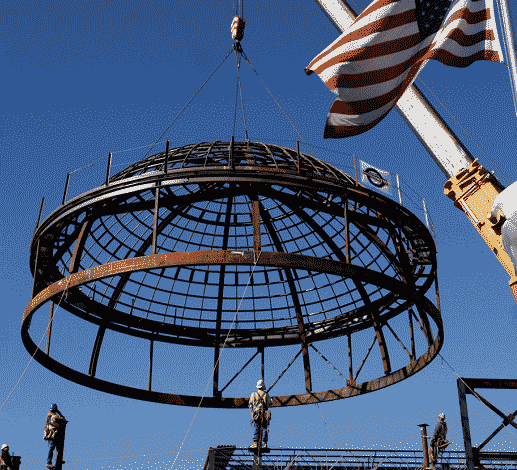
Not unlike the talent of the performers and the tireless rehearsals needed to create the magnificent sound soon to be found in the Kauffman Center, the construction process of the structure required the absolute best contractor partnerships in the industry to orchestrate every detail. Integral to the preplanning and execution of the erection of the structural steel was the 3D modeling and staged analysis of an elaborate 52-stage erection/stability plan created by the Midwest Steel erection team. Twenty-three drawings, by section, were generated for stability bracing, 14 drawings for rigging of all lifts and seven drawings for crane logistics. Critical to the development of the detailed erection plan was a staged load analysis to maintain stability for the partially erected structure. Secondary construction loads were considered to accommodate the follow-on trades during erection as needed.
There were 26 critical lifts planned and executed on this project.
The connection points at the tops of each building were erected several months prior to the erection of the vertically curved trusses.
Control of the position was critical in order to erect the back of the house and close the structure. Jacking frames were designed to stabilize and maintain geometry of the trusses. The front of the house had a continuous curved box truss that ran from one end of the project to the other connecting the exterior structures of the con-cert hall and the proscenium theater. This was considered the most critical geometry on the project and served as the geometrically critical connection basis to the structure for the cable-supported glass atrium that served as the entire front of the structure.
For each lift a critical lift plan was developed and team meetings were conducted to simulate every detail and to be sure every-one understood their roles in the process. The Tekla model was a critical tool for this project. Within the model, Midwest Steel was able to verify piece weight and geometry, determine the center of gravity of the pick piece and to review the swing path for the piece.
Crane staging was verified in relation to the initial staging position, the final set position and to verify a clear swing path. Lay-down areas were coordinated for pre-assembly, trip and set.
A universal lifting apparatus was designed and modified as detailing progressed. Prior to erection, a practice lift was performed to verify crane capacity using the onboard computer and to make sure the swing path was unobstructed. This was a major concern due to the geometry of the building. There were many levels of concrete and steel to navigate the crane boom and picked piece around in order to set each piece. In addition, step-by-step, bullet point directions were created and used by the crew during the lift which kept everyone focused on safety.
Another factor of expertise was appropriate equipment selection to execute the lifts. Plans were developed that reduced crane movement and lowered the sled weights. These details saved time, eliminated the need for a secondary crane, and resulted in safer execution of the lifts.
The Kauffman Center’s structural steel work was completed in
February 2010. The facility is scheduled to be fully operational for the 2011 performance season. For more information, visit
www.kauffmancenter.org.As with all large undertakings, the development of the Kauffman
Center project has been a collaborative team effort. Jon Vinson, who recently completed his 40th year with Hirschfeld, has been a key player from the inception of this project. He spearheaded the realization of the design as it advanced toward the fabrication stage and deserves a lot of credit for its successful completion.
The author also wishes to thank Tom Broad of Midwest Steel for providing information on the erection methodology.
A Many of the connections required multiple connection plates at various angles, posing challenges to both the detailer and the fabricator.


