Traditionally, a project such as this begins with the engineer creating his models in the analysis software. Depending on the complexity of the job, numerous models may need to be invoked.
Once the analysis is completed, redline markups usually follow for the drafter.
On the NRUCFC project, invoking a fully integrated approach within REVIT reversed this workflow process. The goal was to have one model serve two purposes. By implementing a bi-directional link from the analysis software, ETABS, to REVIT
Structure, required starting the model with preliminary member sizes and locations within REVIT. The member sizes, materials, and loads were assigned in REVIT. An internal mapping file was used to help associate the REVIT frame attributes to the ETABS section database.
As changes and modifications to the structure occurred during the design phase, the implementation of the bi-directional link from REVIT Structure to ETABS allowed for ease of review and coordination. By updating the changes once in REVIT and using the bi-directional link, the ETABS model was updated shortly thereafter. The analysis in ETABS was run, reviewed, and then linked back into REVIT Structure with any changes.
Dome Design
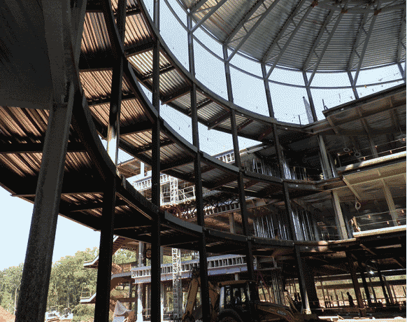
To reinforce the feeling of spaciousness, the three-story atrium was created using tapered curving HSS truss sections. These partially exposed HSS truss members were used to fashion an elegant and sleek look to the dome structure. At the apex of the dome, a
24-ft oculus glass opening was designed to allow natural light to flood the atrium below. Bracing several of the dome columns, a cantilevered walkway from one wing of the building to the other was utilized. The added weight and stiffness of the framing for the walkways helped counterbalance the weight from the dome steel as well as support the dome columns.
The dome was created using a perimeter of 24 wide-flange columns, spaced every 15 degrees around the dome. The top and bottom chords of the truss were HSS8x8x3⁄8 and the web members were
HSS4x4x¼. The dome’s profile and curvature play an important aesthetic role in the building. The dome trusses are visible not only from inside the building, but from outside as well. The HSS trusses taper upward to create the dramatic open feeling at the top of the atrium. Keeping the top chords constant, the bottom chords taper from an outside truss height dimension of 5 ft 6 in. to the inside truss height dimension of 3 ft.
The depth to span ratio for the dome is 1:4. Creating the 24-ft-diameter opening for the oculus glass required top and bottom compression rings. These rings are continuous HSS8x8x3⁄8 members that carry the weight of the truss as well as the weight of the glass. Holding these rings together are vertical HSS8x8x3⁄8 members.
As the rings undergo large compression forces, the trusses transfer the load back to the supporting perimeter columns. These columns then undergo large tension forces exerted by the trusses pushing outward. To resist these forces, the columns are joined together at the top and bottom of the truss by HSS6x6x¼ tension members. These members help stabilize the dome by resisting the outward push.
Dome Connection
The connections for NRUCFC were designed by SteelFab using structural connection design software that was developed by its in-house staff of licensed professional engineers. The HSS dome truss was designed per AISC 360-05, Section K2, with directly welded connections, mainly due to the aesthetic considerations for the architecturally exposed structural steel. All of the HSS truss members were sized such that the limit states of chord plastification and shear yielding (punching) do not control; therefore chord reinforcement was not required. Considering eccentricity in the joint configurations helped to economize the connections by allowing single bevel cuts for all branches and no overlapped joints. The branch connections were primarily made with fillet welds, with partial joint penetration groove welds used as well for the diagonal members.
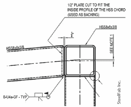
Using CJP welds with HSS members can be challenging, as the preparation and fit-upare more demanding. Therefore CJP welds were used only for the critical joints, such as field splicing the compression ring, which had been fabricated as separate rolled HSS members, and the chord to compression ring connections. The CJP weld was accomplished by providing a ½-in. backing plate cut to fit within the inside profile of the HSS member. The plate was recessed ¼ in. inside the HSS member, allowing for ¼-in. backing at the joint root opening. A typical HSS truss chord to compression ring connection is shown below, followed by a typical compression ring splice connection.
 <<The connection detail for the
 chord connections.
 <<The connection detail for the compression ring field splice.
 <<The added weight of the cantilevered bridges connecting the two wings helps brace the columns supporting the dome and counter-balances the weight of the truss dome.
 Construction
Sequencing and erection also served as a challenge. With its unique shape and difficult location in the building, each truss member was fabricated in the shop. For ease of erection, the columns were spliced below the trusses. That allowed the trusses to be connected to the columns at the shop.
Each truss was then erected and welded to the supporting column below.
Temporary shoring was erected at the center of the dome to support and carry the weight of each truss until final connections could be made. Erecting the entire truss on the ground and hoisting it up was not an option due to limited access for the crane. Once the shoring was in place and temporary connections were made to the truss, the bridge connecting each side of the building was erected. The added weight of the cantilevered bridge not only helped brace the columns supporting the dome, it also counterbalanced the weight of the truss. With the dead weight of the bridge offsetting the weight of the truss, it was important to allow the truss to deflect and the columns to rotate until the bridge was in place. Once completed, temporary connections were removed and permanent welded connections were made. Scaffolding was then cut down piece by piece, removed, and the building was ready to be enclosed.
The structure is expected to be completed in July 2011. Even though the project did not employ Jeffersonian design or construction techniques, the gentleman from Virginia no doubt would have been pleased to have NRUCFC join the neighborhood.
No hay comentarios:
Publicar un comentario